Ability to directly control the GPIO (general purpose input output) pins is one of the reasons the miniature Raspberry Pi is so famous with hobbyist and educationalists.
In this self learning exercise, I will read the status of the button, determine if it is pressed or not and then based on that, switch the LED on or off.
Very basic right? Let’s follow along.
Components
- Raspberri Pi 2 Model B (40 pin) with Raspbian OS
- Breadboard
- Connectors
- LED 5mm
- Push Button
- Resistors – R1 (330 ohm) & R2 (1K ohm)
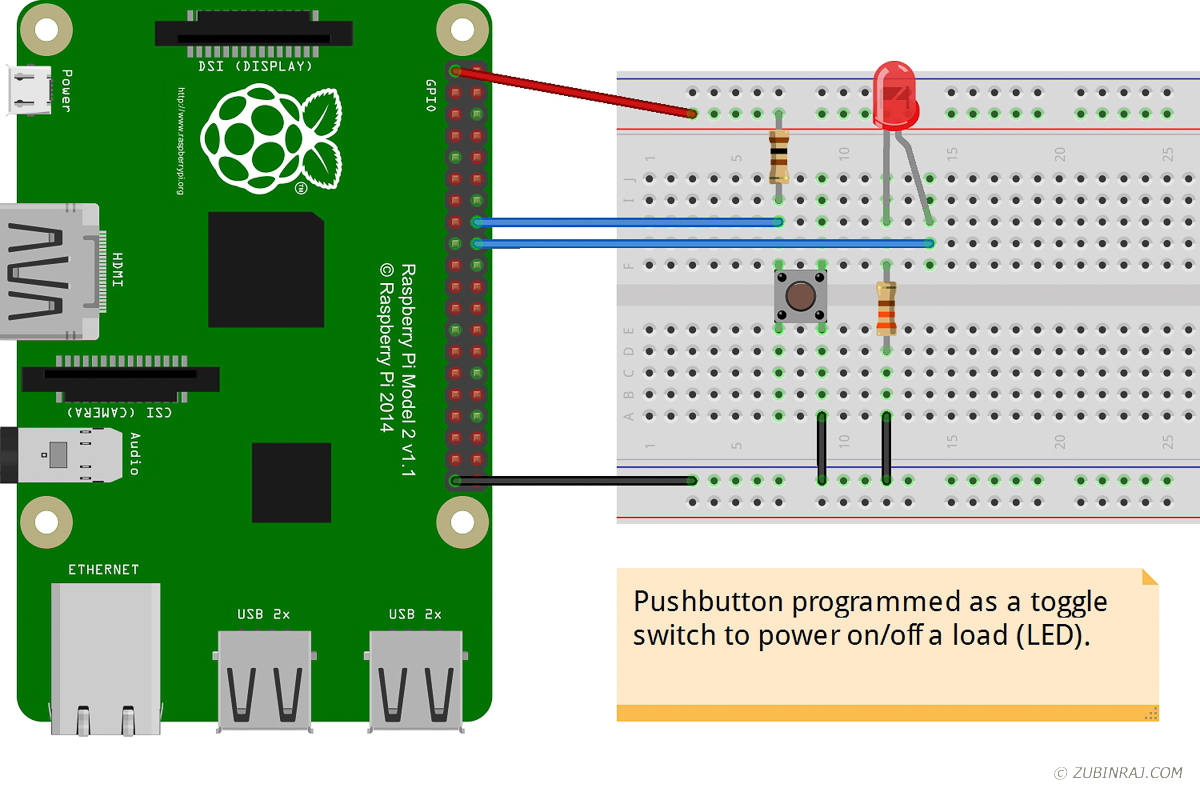
Wiring It Up
My setup uses the GPIO 23 (pin #16) and GPIO 24 (pin #18), however you can use any GPIO pins for this purpose. If you are using different pins, make sure to update the pin numbers in the program below.
- GPIO 23 (pin #16) – Used as input to read the status of button
- GPIO 24 (pin #18) – Used as output for switching the LED on and off
- +3.3V (pin #1) – Connected to power rail on the breadboard
- GND (pin #9) – Connected to ground rail on the breadboard
- R1 – Connected between LED and ground
- R2 – Connected between 3.3V power rail and button
Program
You need a program to tie these hardware together; to read the status of the button and send the signals to light up the LED.
I used ‘C’ with WiringPi libraries. I’m quite new to these myself. If you prefer, you can also do the same with Python. Geany is my favorite editor on the Raspberry Pi, works for both C and Python.
Let me quickly explain the functions of WiringPi library used in the program:
digitalWrite() – used to send an output to the GPIO pin. The first parameter is the pin number. Second parameter determines if the pin should be set as either HIGH or LOW (it can take only 2 states).
digitalRead() – used to read the status of the GPIO pin. The only parameter passed is the pin number. The output is either HIGH or LOW and can be checked as below:
|
1 2 |
if ( digitalRead (pin) ) // this means the button is not pressed or is open { } |
|
1 2 |
if ( !digitalRead (pin) ) // this means the button is pressed or is closed { } |
Once this part is understood, whipping up a code to capture the pressed state of the button and lighting up an LED is a piece of cake. Not joking, it really is!
The next part is how to toggle. This is done by remembering the previous state of the button and when it changes, determine whether to switch the LED on or off.
|
1 2 3 4 5 6 7 8 9 10 11 12 13 14 15 16 17 18 19 20 21 22 23 24 25 26 27 28 29 30 31 32 33 34 35 36 37 38 39 40 41 42 43 44 45 46 47 48 49 50 51 52 53 54 55 56 57 58 59 60 |
# include <wiringPi.h> void ledOn(int pin) { digitalWrite (pin, HIGH); } void ledOff(int pin) { digitalWrite (pin, LOW); } int main (void) { const int BUTTON = 23; // GPIO 23, pin #16 const int LED = 24; // GPIO 24, pin #18 // initial setup wiringPiSetupGpio(); // set the pin mode as either INPUT or OUTPUT pinMode(LED, OUTPUT); pinMode(BUTTON, INPUT); int state = 0; // initial state int press = 0; int prev = 0; int val; while (1) { if (!digitalRead(BUTTON)) press = 1; // pressed else press = 0; // not pressed // at every button press, toggle the state if ((press == 1) && (press != prev)) state = !state; // store prev value prev = press; if (state == 1) ledOn(LED); else ledOff(LED); // add delay to avoid the bounce delay (75); } return 0; } |
Since the program involves low level access to gpio pins, it will need ‘sudo’ permissions to run this program.
Summary
Here, we saw how to read input from a button and write output to light up an LED using the GPIO pins of a Raspberry Pi. Once we have these basics right, then the same knowledge can be used to drive other loads like a relay, motor etc.
References
WiringPi – GPIO interface library for the Raspberry Pi
WiringPi GPIO Pins – Pin layout for WiringPi specific and Broadcom specific pin modes
Adafruit – Tons of stuff related with Raspberry Pi and Arduino